Currently, I’m building an RC transmitter/receiver based on the SX1280 RF chip. One of the goal for the project is that I want 12 bit servo resolution from the sticks all away down to the servos. Partly because modern digital servos have 12 bit resolution secondly a high-end transmitter is using 12 bits anyway. I was investigating how I can generate high resolution PWM signals on STM32 devices. I’m using black pill (STM32F103C8T8) at the moment for the prototype.
Hardware
- Any STM32F103 development board (blue pill, black pill, etc.)
- A USB power bank as power supply
- STM32 programmer (Segger j-links, ST-LINK/V2, or simply an st-link clone)
Software
- STM32CubeMX
- Atollic TrueSTUDIO for STM32
- Project source from github
The Obvious Solution
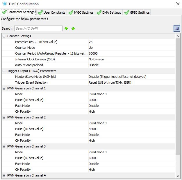
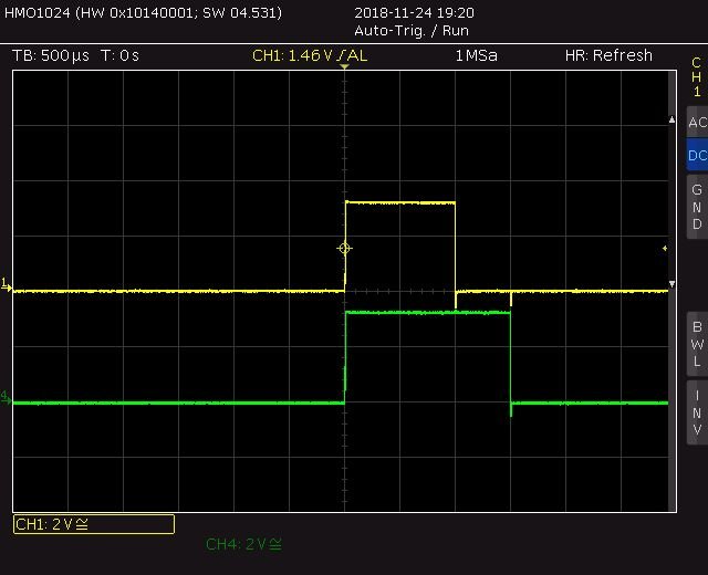
Probably the easiest solution is to use one of the timer which can generate PWM signals, like TIM1-3 on an STM32F103. For a modern digital servo the frame rate can go down to 5 ms or so, but for an old analog servo it should be 20 ms or 50 Hz. So, as a worst case scenario let’s generate that. With 72 MHz clock and 16 bit timer counter resolution we need to set the timer’s prescaler to minimum 23 in order to cover the 20 ms frame rate. I selected 24 because then for 20 ms I need to set the counter exactly to 60000. You can see the CubeMX setup and the generated 1 and 1.5 ms PWM signals in the screenshots. Unfortunately, for 1ms the timer’s counter should be set to 3000, which would give us only 11 bit resolution. Not bad, but the goal was 12 bit, so let’s try something else.
Of course If I would select a micro controller with 32 bit timer counter, like STM32L476 this resolution can be much higher and the problem would be solved.
But here, I would like to propose an alternative solution which will further increase the resolution even on the STM32F103.
Cascading Timers for Higher Resolution
The main problem with previous solution is that the frame rate (20 ms) is relatively high compared to the actually generated PWM signal (between 1 and 2 ms), so we are wasting some valued bits for the remaining 18 ms when we are waiting for the next frame. This can be solved by cascading timers using the timer link feature for synchronization.
The idea is that I’ll use TIM1 as master to generate the frame rate (20 ms) and TIM2, TIM3 to cope with the PWM signals as slaves. When the master triggers the slaves they only generate a PWM signal in one pulse mode. Therefore I only need to cover 2 ms in those timers. Luckily you can cascade those timers in hardware so this synchronisation does not need any intervention from the processor and it is very precise too, the jitter is in the ps region. You can see the CubeMX setup on the following screenshots:
As you can see I selected 3 as prescaler so for the 2 ms I need to set 48000 in the timer’s counter. This gives us 24000 for 1 ms which is more what we need for 12 bit resolution. Actually, we can use 14 bits to set the pulse width. Tadaaaa…
Please take a look at the oscilloscope screenshots for the final result. The channel 3 (purple) is the master timer’s interrupt which will trigger the salves to generate one pulse. Channel 1 and 4 (yellow and green beam) are the actual PWM signals generated by different timers. Note that they are in sync but they are synced at the trailing edges, that is because of the PWM mode 2. This is not a problem, because the PWM rate for the particular servo is still correct.
Other benefit of this solution is that to change the frame rate would mean to change the period in TIM1 only. For modern digital servos you can go up to even 200-300 Hz, but please consult the servo’s manual if you wanna fine tune.


