
Most of the RC current sensor designs are using a hall effect-based current sensor, like the ACS758. In this project I would like to try something different (more difficult?) and use a conventional high-side current sensor to achieve the following goals:
- Maximum 60A continuous current sensing capability,
- Maximum 5S (18.5V) LiPo battery input,
- Send telemetry data (current, voltage, power and capacity) to my Jeti DS-24 transmitter,
- Lightweight, small (and cheap) design
Hardware design
In the project I used an STM32G431KBU which is a powerful 32bit processor in a small package (LQFP32). It is too much for this job, but I bought them in bulk because I would like to use them in other projects too.
The design based on a high-side current sense amplifier: MAX4081. The current from the battery to the speed controller flows through a precision high power current-sense resistor (CSS2H-3920R-L200FE) which is sensed by the MAX4081. The current-sense resistor dissipates its own I2 × R loss, so for 60A it would be 0,72W which can easily be handled by that resistor. The gain of the current sensor amplifier is 60V/V this sets the maximum load current at the full-scale sense voltage to ±125A (yes, it’s bidirectional!). Theoretically the current-sense resistor could also handle that load, but the XT60 connectors used in the design limits the current to 60A anyway. The voltage output of the MAX4081 corresponds to the sensed current (VOUT = VREF ± RSENSE × ILOAD(MAX) × AV) and is feed to the CPU’s ADC. The reference voltage for the MAX4081 is generated by the DAC of the CPU.
The analog section of the CPU is powered from an MCP1501 reference voltage (3V) to achieve adequate precision for the DAC and ADC.
Using a resistor voltage divider the ADC can also measure the battery voltage. At the moment the divider is set that the maximum voltage can reach 50V. From the current and voltage the power is calculated and with a help of a timer the used capacity can also be calculated reasonably well.
The complete hardware design is on github.
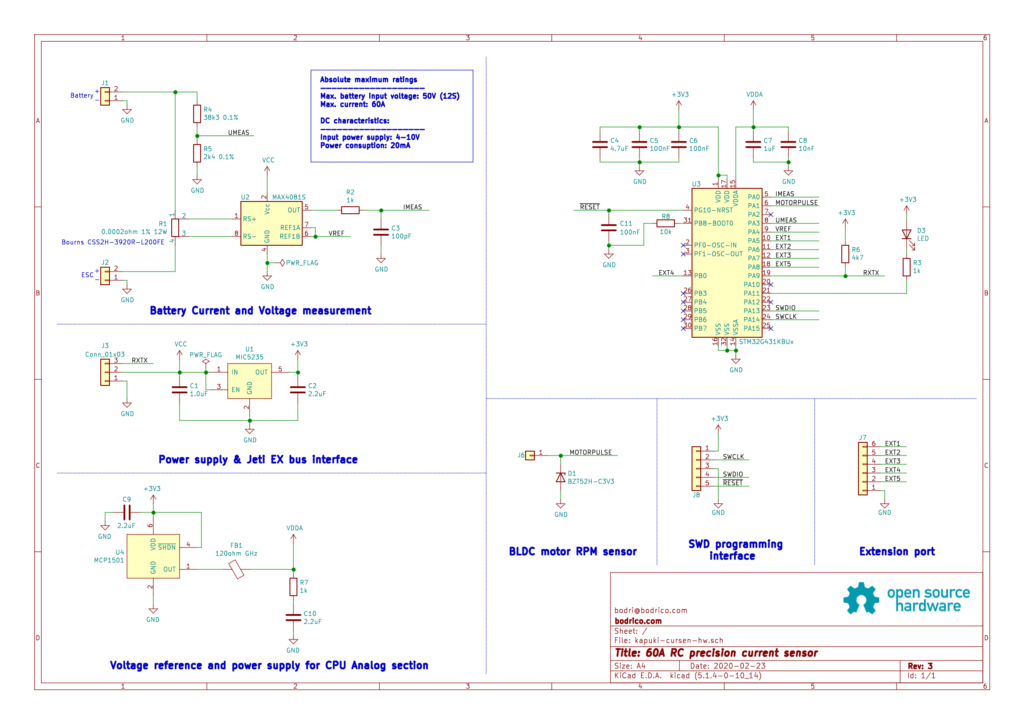
Note: the schematic displayed is rev.3 already which fixes two small issues, but those changes are not incorporated to the PCB design yet:
- The SWDIO and SWCLK is mixed
- The layout for the servo connector pins a bit inconvenient (the signal and positive power pins are swapped)
Anyway, they are small issues so if you want to rebuild the device you can order the PCB from OSH Park. The fully assembled rev.2 PCB as shown here:
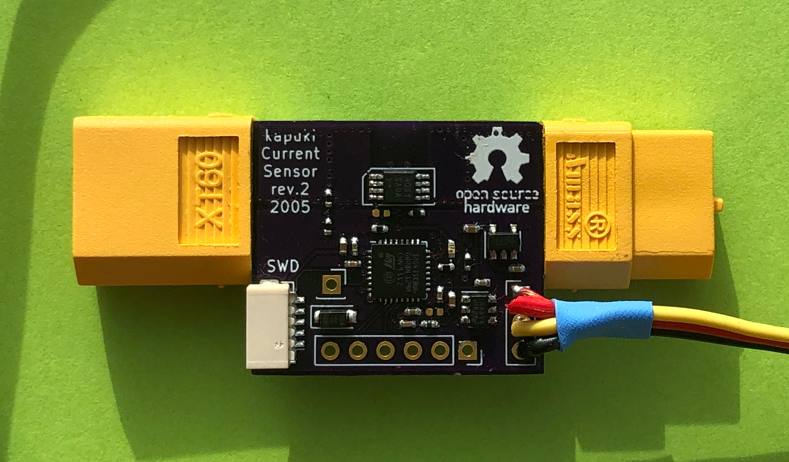

Note that the ground connection wire is not soldered yet between the two terminals of the XT60. You really need a beefy wire there, because the PCB is not designed to handle 60A or so.
Software architecture
The software is very simple: after the initialisation of ADC, DAC and serial port of the CPU the ADC automatically reads battery voltage and current. A timer interrupt routine stores those readings in a local variable in every 10 millisecond. In the main loop the serial port scans for Jeti EX bus telemetry request and sends those measured values (current, voltage) along with the calculated ones (power and capacity) in the necessary format.
At the moment the sensor only supports Jeti EX bus protocol, but any other protocol can easily be implemented.
The firmware can be found here: github
Conclusion
The voltage measurement pretty accurate and does not need any calibration. For the current measurement the reference voltage generated by the DAC needs some calibration: set the DAC output to a value that the measured current is 0 with no load (it’s 2031 in my case). I have no electronic load capable to test more then 12A, but in that range the circuit measured the current also very well. Once the weather allows me I’ll test the circuit in my plane.
In terms of weight the device is 14 grams, but half of that weight is from the XT60 connectors. All the components and PCB set you back around €15 per device which is way less than any commercially available product with similar specification. And top on that you can hack it in the way you would like to.
Dear bodri,
I am very glad to find this interesting RC accessory. I downloaded the project file from github and I can open it by stm32cubeide v1.4, I also can rebuild the project with a good result: 0 erros and 0 warnings. But, I can’t “Debug” and “Run”, there are always errors:“Error in final launch sequence:Failed to execute MI command:” ,although I used a st-link v2 and a stm32g431kb develop kit board which I can guarantee that they are in good condition. At the same time, I can’t also download the HEX file made by the IDE to the target board by stm32cube programmer software. But if I tried to download the HEX file which you packaged in the project file, then everything is OK. I‘ve compared two HEX file,they are different.
So I think that the problem may be caused by incorrect configuration of STM32cubeide, including Build, Debug and Run configurations.This is my first time to use STM32cudeide.
I hope you can help me.
Thank you very much!
Regards,
Eric
Hi Eric,
I’ve never seen that error. My github project should include everything (also settings) you need. I also guess that this is something with your Debug and Run configuration. I’ll send you a screenshot of my settings via an email. I hope that will help. At the moment I’m considering to revisit this project because I need some more current sensors and I would like fix the errors on the PCB I had with rev.2. I also received some feedback that the board is not so easy to replicate so this time I will use 0603 components and LQFP CPU to make it more hand solderable.
I really like your projects! At first I was just interested in your RC Current Sensor project but then I started reading about your other projects and I got hooked. I’ll be sure to check back here when you have new or updated projects.
Hi Paul,
Thanks. Unfortunately I don’t have that much time as I would like to spend with my hobbies nowadays. Currently, I’m working on a new version of the current sensor with better temperature drift and I also had some progress on my “dream” to build a high-end RC transmitter from scratch. I hope I can post some new stuff this winter.