Mostly high end RC transmitters/receivers are using the good old CC2500 chipset. When you hear SX1280 probably the first word pops in your mind is LoRa. However SX1280 chip also supports FLRC mode which is very similar to MSK used on CC2500, but according to the documentation SX1280 does it with 16 dBm higher receiver sensitivity at ~250kBaud data rate with FEC.
Earlier I did a combined redundant (with two CC2500 module) transmitter and receiver, which I did not document unfortunately. Maybe I will revisit that project later, but now in this project I would like to use two SX1280 modules instead.
Project goals
- Handles both receiver and transmitter in one codeline/hardware
- FHSS (Frequency Hopping Spread Spectrum) system
- FCC and ETSI EN compliance
- 80 channels (on normal ISM band: 2400 Mhz – 2483.5 Mhz), with 1MHz channel spacing
- 100 Hz hopping frequency
- Fixed hopping sequence
- Simple acquisition and tracking between the transmitter and receiver
- No binding process; the transmitter and receiver hard-bound together
- Fixed packet length
- Transmitter sends basic control functions on at least 16; 12 bit channels
- Receiver can also send telemetry data back
- RSSI (Received Signal Strength Indicator)
- Receiver battery voltage
- Relative altitude
- Vario
- Absolute orientation
- Built in GPS support
- Extensible via UART port(s)
- Built-in sensors
- BNO055: Intelligent 9-axis absolute orientation sensor
- BMP388: Digital pressure sensor
- CAN bus
- OTA (Over the Air) firmware update
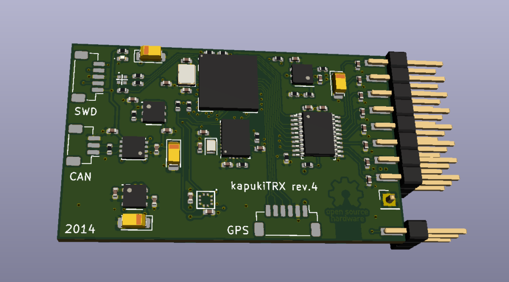
Hardware design
I tried to miniaturise the hardware as much as possible, first of all to lower the weight and secondly to make the PCB manufacturing costs low. Therefore I used 0402 size passive components and BGA packaged CPU. If you want to build the project the PCB can be ordered from OSHPark directly or from JLCPCB with this gerber file. Please note that this is not a beginner project you need the necessary equipment and practice to successfully assemble this board. I also ordered stencil from OSHStencil to speed up the assembly.
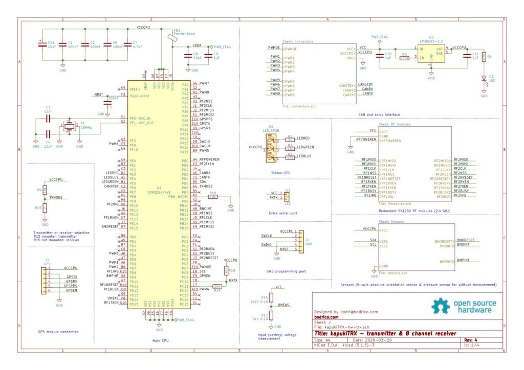
The complete hardware design can be found here: github.

CPU
I used the brand new STM32G474 as the main CPU, which has enough power to control the transceiver modules, servos and process sensor data simultaneously. Because the fair amount of peripheral I needed to use one of the 100 pin packages. To keep size smaller I chose the 100 pin TFBGA version. This package has 0.8mm pitch which is suitable for fanout with 5/5mil PCB technology that OSHPark can manufacture.
Status LED
I used a normal green LED to indicate when 3.3V is present on the CPU power rail. In addition an RGB LED used to indicate receiver/transmitter status:
- Blinking green: Waiting for connection
- Green: Connected
- Blinking red: Connection lost
- Red: General hardware failure
Power distribution
As usual the board is powered from any of the servo connectors. The operating voltage should be between 4.5-9V. I used LP38693 LDOs to create the necessary voltages for the board, actually tree of them:
- 5V for CAN bus and servo signals
- 3.3V for the SX1280 modules
- 3.3V for the rest of the board
The SX1280 modules have got their separate LDO because during transmission they can consume 150mA each. That would be 300mA out of the 500mA that LP38693 can produce, so not much room for CPU and the rest of the board. I didn’t want to limit the design that I can only transmit on one of the SX1280 module at a time.
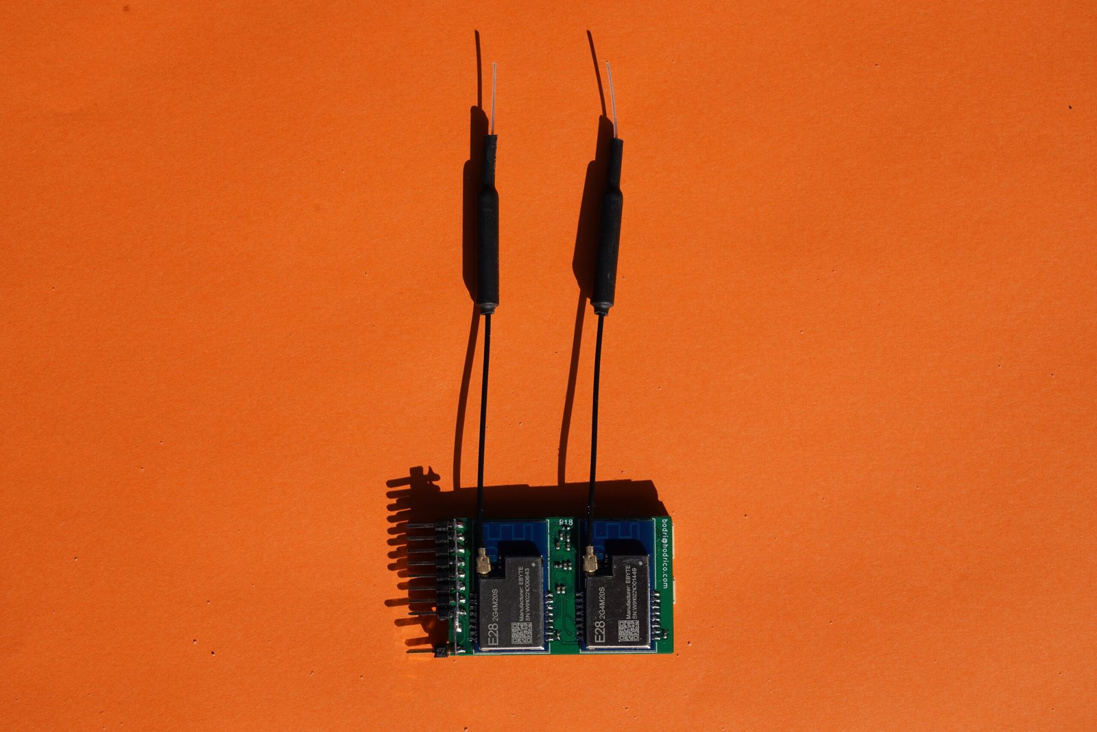
RF Modules
I used two of an SX1280 module from CDEByte (E28-2G4M20S), which can be ordered via ebay.
Servo connections
The standard voltage for an RC servo signal is 5V in order to serve old TTL logic based servos, probably modern servos can work with 3.3V too. The CPU PWM signal is only 3.3V so I used a TXB0108 voltage level shifter to convert it to 5V. In this way I could also share the 5V power rail with the CAN bus driver. To generate the PWM signals I used two of the CPU’s general purpose 32 bit timers.
CAN Bus
I used a very simple design around an MCP2562 high-speed CAN transceiver.
Sensors
I designed the module in the way that an external (UART) GPS can be easily connected, which can provide telemetry data like model distance, speed, etc. Although, this can also measure altitude, it’s not very precise, so I wanted to enhance that with a pressure sensor. I also wanted to try the BMP388, so I thought I’ll give it a go. The other sensor is a BNO055 absolute orientation sensor, which might be useful to incorporate a flight assistant functionality into the receiver or gesture recogniser into the transmitter.
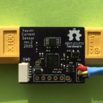
I’m also working on a current sensor, which can be connected to the extra telemetry port. With that extra sensor I will have all (and more) telemetry data I currently use in my airplanes:
- Receiver battery capacity used
- Receiver battery voltage
- Current, power
- Relative altitude
- Model distance
- Speed
- Vario
Hardware status
As of now (July 5, 2020) the following hardware elements are validated to work:
- All power rails
- CPU
- Both SX1280 modules
- Servo signals
- BNO055 is working on 0x28 I2C address
- BMP388 is working on 0x77 I2C address
Not validated yet:
- Battery receiver measurement
- CAN bus
- GPS port
- Extension port
Firmware
Of course this is the part where I need more work. It’s far from finished. At the moment basic functionality works:
- Both SX1280 modules are used. In transmit mode I alternate them while in receive mode they are both listening.
- Acquisition works: the receiver jumps to a random channel and scans through the channels 3 times slower than the transmitter. Eventually, the transmitter catches up with the receiver. In tracking the receiver adjusts its heartbeat timer to the received packets, to make sure that the transmitter and receiver will not drift out of sync.
- From the transmitter point of view every 4th packet is a downlink or with other words the receiver sends a telemetry packet.
- Communication with both the BMP388 and BNO055 works. I added a little C++ wrapper around the library that Bosch provided
Take a look at it in my github.
Conclusion
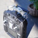
First of all and most importantly I really enjoy this project. The hardware really looks and works as any commercially available product (jeti Duplex REX10A). On the software side is still a lot to discover. I don’t dare to use it in an airplane yet, because it needs lot of testing.