Experimentation with vacuum tubes requires a high voltage power supply, typically 200-400V DC. Most hobby labs are not equipped with such a device. This step-up converter allows you to boost up your benchtop 0-24V variable DC power supply to a high voltage power supply.
Design
My original intension was to create a stand alone high voltage power supply, but for that I need to solve the voltage and current control mechanism. For a proof of concept I decided to start with a simple step-up converter, where all the control happens on the primary side using a variable DC power supply. Therefore I chose a full-bridge topology, which I can easily convert to a phase-shifted full bridge (PSFB) DC-DC converter. I even started to do so with the software implementation: it is already using phase-shifting, but at the moment the shift is fixed 180°. Later that can be controlled by a PI controller or a 2P2Z compensator which is using the output voltage. For the current control I would like to use an average current control mode technique on the primary side. I also planned to add a linear regulator after the switch mode regulator to lower the output voltage ripple.
On the secondary side I used a full-bridge rectifier circuit using ultrafast rectifier diodes, thus no center-tapped transformer was needed. This makes the handmade transformer winding much easier. I also added a simple LC filter to the output.

Transformer calculation
I selected a PQ26/25 core with N97 ferrite material, which can handle 1300-2000 Gauss peak flux density without saturation. For the calculation I will use 1600 Gauss. This core has 1.222 cm2 effective cross section. I will use f = 100kHz and a maximum input voltage of 24V:
I rounded it off to 3 turns on the primary side. When we feed back that value into the equation we get 1636 Gauss, which is well within the acceptable range of maximum flux density. From the selected primary turns we can calculate the secondary side:
My goal was to get 400V DC on the secondary winding. To be on the save side I added a little bit of margin, so I’ll use 440V in the calculation. The maximum duty cycle is 94%, because dead time takes 6% of the total cycle, therefore the input voltage to the transformer is 0.94 * 24V = 22.56V.
I rounded it off to 58 turns.
Construction
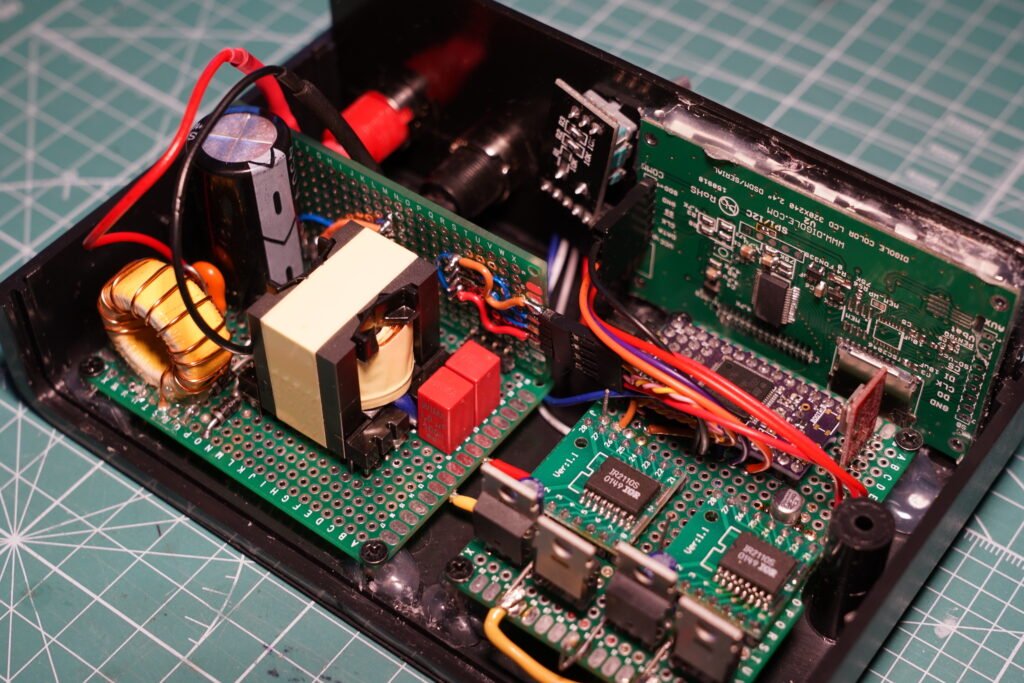
I built the power supply on two prototyping boards; one for the primary and an other one for the secondary side. I used mostly components from my junk box both through hole and SMD (they are mostly on the bottom side). For the control I used an STM32L476 Dragonfly board, which I build myself some time ago using an OSHPark board. Unfortunately, I needed to use two different timers – because of pinout limitations – to control all 4 PWM signals, but I managed to synchronise them to create the appropriate phase-shifted signals.


Note the additional circuitry: an AMC1311 to measure output voltage in an isolated manner; a display and a rotary encoder. More about that in part II. Those components are not necessary I added them to play with the original concept of a PSFB design. I actually managed to add a PI control loop to set the phase-shift to tune in to the target output voltage – as you can already see in the source code. To see the simple booster code: check out this commit.
Using the calculations above you can also modify the circuit to change input and output voltage ranges. I also built a 0-300V version, which is only different with its transformer windings.
Transformer winding

Essential tools and components 
Primary winding is started; note the margin tape 
Primary layer is covered 
Second layer of the secondary winding 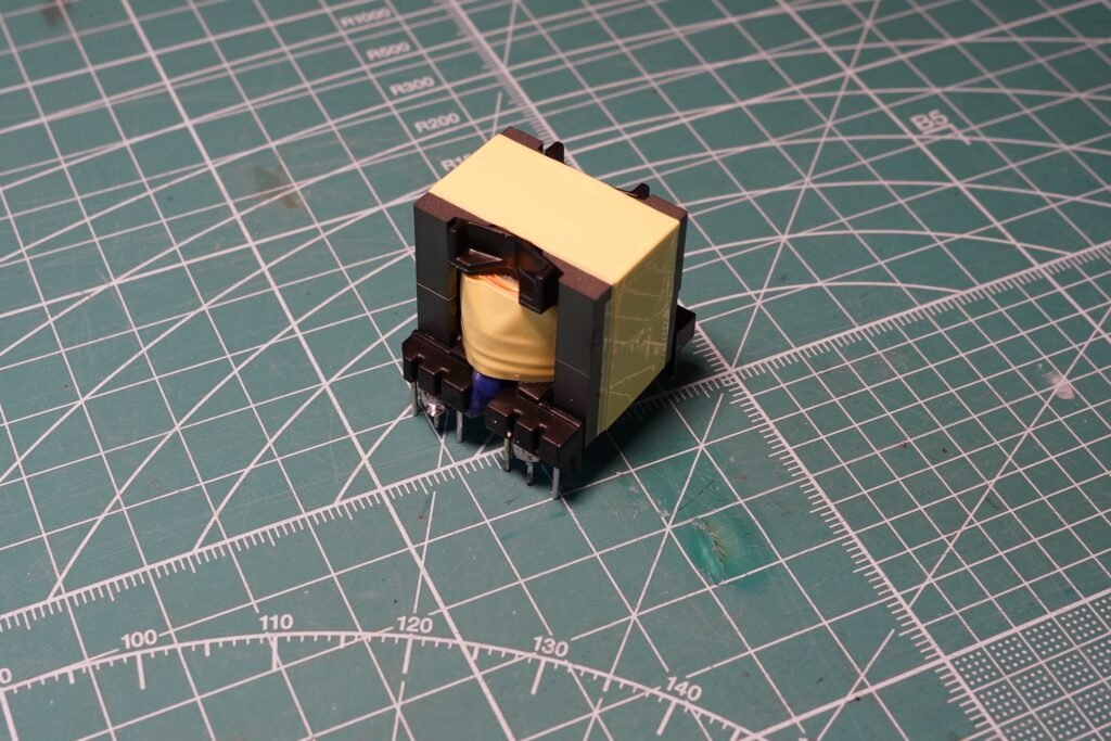
The finished HF transformer
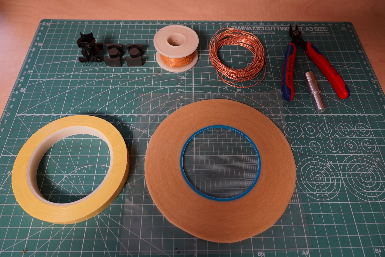

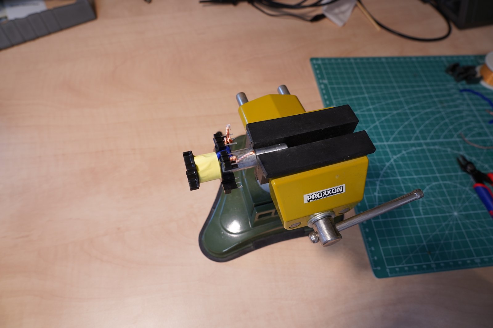
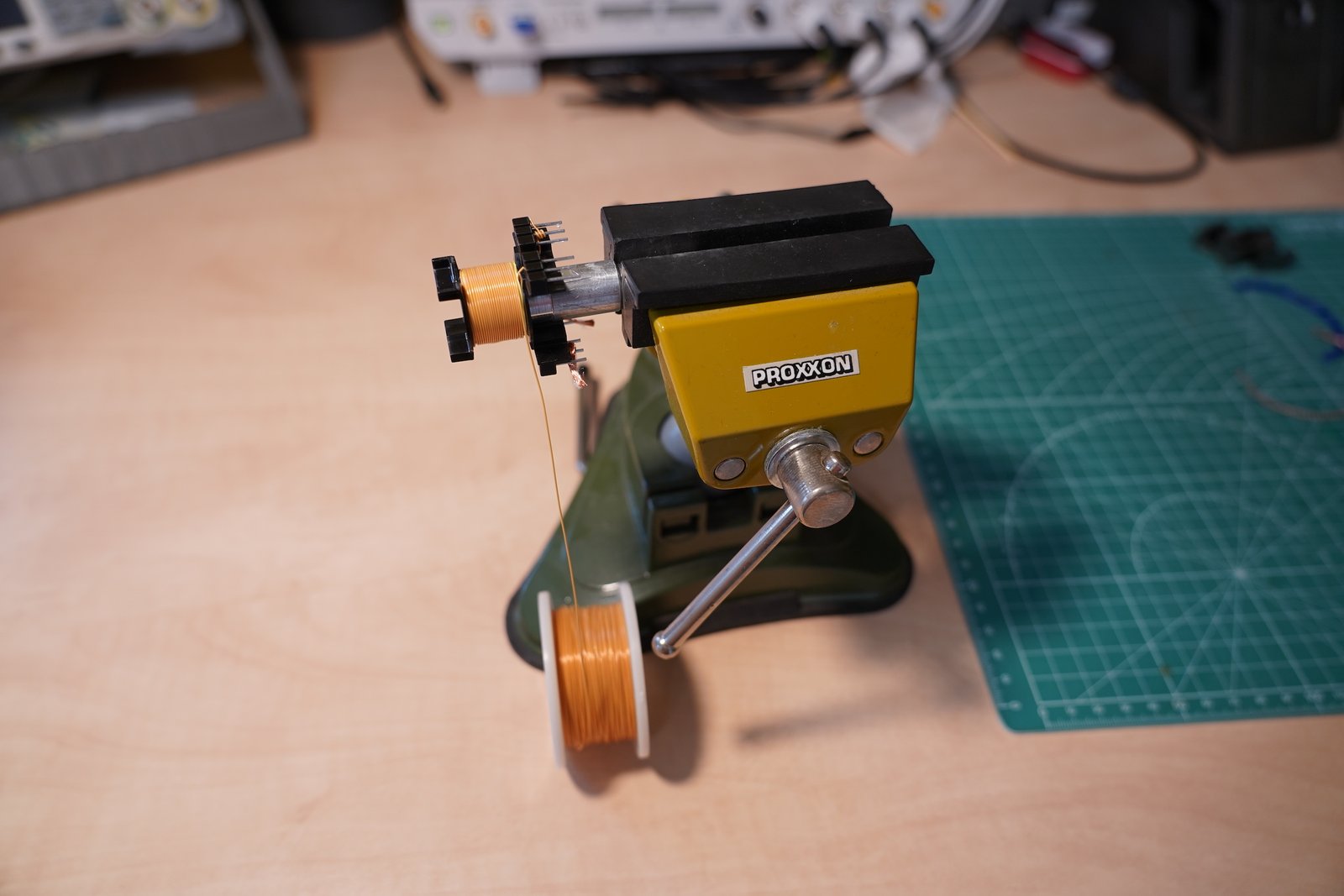

As I mentioned earlier it is a pretty simple 1S1P transformer. I started with the primary winding using an 1.2 mm diameter litz wire (no clue about the number of wire strands). I added 2×2 mm – 4 mm total – margin tape on both sides of the bobbin and winded the 3 turns. I insulated the primary winding with 3 layer of mylar tape. For the secondary side I used a 0.4 mm diameter triple insulated transformer wire (the core diameter is 0.28 mm). This will add extra security between primary and secondary windings. This fitted in three layers (24 turns per layer) which I insulated with one layer of insulation tape between them. I covered the whole transformer with a final three layer of insulation tape. I don’t have insulation varnish, but it seems the transformer is fine without that. It looks like a commercial counterpart.
Operation
At the moment the booster needs two separate input voltages: 12 V / 100 mA for control and 0-24 V to boost up. Operation is very simple: change the input voltage to get the expected output voltage. Because the lack of feedback the no-load output voltage is different than on load, therefore you need to adjust it accordingly. I tested my circuit with heavy load (40W incandescent bulb) and it works very well. The booster can easily handle 40W, I’m not sure about the transformer maximum, but I guess it is somewhere around >50W. So, 100mA for 400V is no problem, of course you need almost 2A on the primary side to achieve that. Again, the current control also happens on the primary side, so some measurement or calculation is needed for the correct set up. The output voltage ripple is around 1-2 V peak to peak; you can clearly see the ringing on the output when the MOSFETs are switching on the primary side.

This design produces a lethal, high DC voltage and also supplies a reasonable level of current. You should not proceed with this high voltage project without knowing the basic safety precautions and procedures and without previous experience. By building this project, you acknowledge the risks involved in its operation and accept those risks as a result. I will in no way be held responsible for your actions.

Well done sir, i appreciate your work thank you so much this design helped me lot. I am trying to design 0-400V DC 2 Amp. Can you guide me please.